The Qualification Gap: Why Thermal Cycling Tests Pass in the Lab and Fail in the Field
There is a particular kind of failure that haunts electronics manufacturers: the kind that does not appear during qualification testing, passes all functional checks at the production floor, ships to the customer, and then fails six months into deployment. When the failure analysis comes back pointing to thermal fatigue—cracked solder joints, delaminated vias, or fractured component terminations—the engineering team faces an uncomfortable question. How did this pass our thermal cycling qualification?
The answer, more often than the industry acknowledges, is that the qualification test was not testing the right thing. Standard thermal cycling profiles, drawn from IPC, JEDEC, and MIL-STD specifications, are designed to represent a broad statistical distribution of use environments. They are not designed to replicate the specific thermal biography of a PCB mounted in a diesel engine compartment in Minnesota, an avionics bay over the Mojave Desert, or an industrial motor drive in a steel mill in Pennsylvania. When real-world conditions diverge from the assumed profile—as they frequently do—the qualification result loses its predictive value.
What Standard Profiles Actually Measure
The most widely used thermal cycling standards specify a temperature range, a ramp rate, a dwell time at each extreme, and a total number of cycles. IPC-9701, for example, defines several condition categories intended to represent different application environments. JEDEC JESD22-A104 provides similar structure for semiconductor-level testing. MIL-STD-810 addresses a broader range of environmental conditions for defense applications.
These standards represent genuine engineering consensus and are far preferable to no standardized testing at all. The limitation is not in the standards themselves but in how they are applied. A PCB designed for automotive underhood use may be qualified against a profile that cycles from -40°C to +125°C over a two-hour period. What that profile does not capture is the rate at which temperature changes in an actual engine compartment during a cold start on a January morning in Chicago—a rate that can exceed 30°C per minute and produce thermal gradients across a PCB assembly that no standard laboratory profile replicates.
Ramp rate matters because it determines the magnitude of thermal shock experienced by solder joints, via barrels, and the interfaces between components and their substrates. A slow, controlled ramp distributes thermal stress gradually. A rapid ramp concentrates it. The difference between a 5°C-per-minute ramp and a 30°C-per-minute ramp is not merely quantitative—it can shift the dominant failure mechanism from fatigue accumulation to acute cracking.
The Edge Cases That Standard Testing Misses
Beyond ramp rate, standard thermal cycling profiles typically assume a relatively uniform temperature distribution across the PCB assembly. Real-world thermal environments are rarely uniform. An automotive ECU mounted near the exhaust manifold may experience a 40°C temperature differential between its upper and lower surfaces during normal operation. An aerospace PCB in an avionics bay may be exposed to rapid altitude-driven pressure and temperature changes that interact in ways that ground-based testing cannot fully replicate.
Power cycling is another variable that standard thermal cycling often fails to capture adequately. A PCB that is thermally cycled by the environment while simultaneously generating internal heat from active components experiences a compound stress state. The thermal gradient between a power component and its surrounding board material may be far more damaging than the ambient temperature swing alone. Standard chamber-based thermal cycling typically does not apply power to the assembly under test, which means the internal heating contribution to solder joint stress is absent from the qualification data.
Moisture interaction is a further complication. In humid industrial environments, thermal cycling drives moisture into and out of PCB laminates and component packages in a pattern that can accelerate delamination and ionic contamination. A dry-chamber thermal cycling test does not reproduce this mechanism, which means products destined for humid climates may pass qualification under conditions that do not represent their actual operating environment.
How Environmental Simulation Is Evolving
The more sophisticated test laboratories in the United States are moving toward combined-environment testing protocols that attempt to more faithfully replicate real-world conditions. Combined thermal, vibration, and humidity chambers allow simultaneous application of multiple stressors, producing failure modes that do not emerge from sequential single-stressor testing.
Highly accelerated life testing, commonly referred to as HALT, subjects assemblies to temperature extremes and vibration levels well beyond the specified operating range, with the goal of identifying failure mechanisms before they become field failures. HALT is increasingly being used not as a pass/fail qualification tool but as a design feedback mechanism—a way of discovering where a PCB design is vulnerable before production commitments are made.
Finite element analysis simulation has also advanced to the point where thermal stress in solder joints and via structures can be modeled with reasonable accuracy across complex temperature profiles. Running FEA simulations against application-specific thermal profiles—rather than standard qualification profiles—during the design phase allows engineering teams to identify stress concentrations before they become field failures. This requires that the design team have access to realistic application thermal data, which in turn requires collaboration between the PCB designer, the system integrator, and the end customer.
Design Adjustments That Actually Reduce Thermal Stress Failures
When simulation or field experience reveals a thermal cycling vulnerability, the design response options are more varied than many engineers initially consider.
Solder joint geometry is among the most influential variables. Taller solder joints distribute thermal strain across a larger volume, reducing peak stress at the interface. For large, leadless components—QFNs, BGAs, and similar packages—which are particularly vulnerable to thermal cycling failures, the solder paste volume and stencil aperture design have a direct impact on joint height and, consequently, on fatigue life.
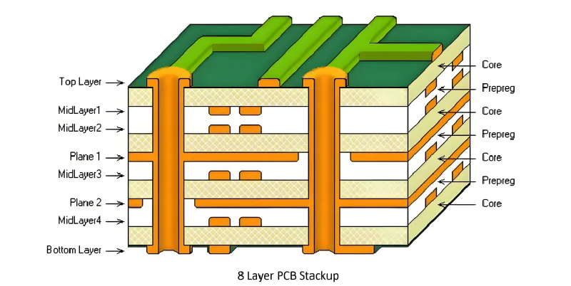
Via design is equally important. Solid-copper-filled vias tolerate thermal cycling significantly better than hollow via barrels, because the copper fill eliminates the barrel wall as a stress concentration point. For high-reliability applications, specifying filled and capped vias in thermally stressed areas of the board is a meaningful reliability investment, not merely a fabrication preference.
Component placement strategy can reduce thermal gradient effects. Placing high-power components symmetrically relative to board fixturing points, and avoiding configurations where large thermal mass components are adjacent to small, flexible ones, reduces the differential expansion stresses that drive fatigue failures.
Laminate material selection also plays a role. Standard FR-4 has a relatively high coefficient of thermal expansion in the Z-axis—the direction that places the greatest stress on via barrels during thermal cycling. Low-CTE laminates, including some polyimide and ceramic-filled materials, reduce this stress at the cost of higher material expense and, in some cases, more challenging fabrication requirements.
Closing the Gap Between the Lab and the Field
The qualification gap between laboratory thermal cycling results and field reliability is not inevitable. It is the product of a design and test process that prioritizes compliance with standard profiles over fidelity to actual application conditions. Closing that gap requires earlier engagement with application-specific thermal data, simulation practices that model real-world ramp rates and power cycling effects, and design decisions that treat thermal robustness as a primary engineering objective rather than a post-layout verification step.
For American manufacturers serving automotive, aerospace, and industrial markets—sectors where field failures carry significant warranty, liability, and reputational consequences—the investment in application-faithful thermal validation is not optional. It is the engineering foundation on which long-term product reliability is built.