Certified to Fail: Understanding Why Boards That Pass Qualification Break Down in the Field

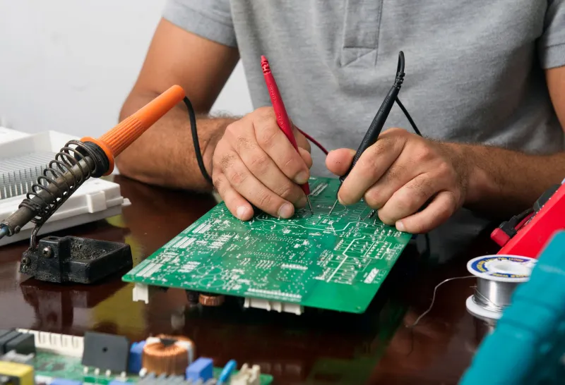
Photo by Photo by Laurens van der Drift on Unsplash on Unsplash
The Illusion of a Passing Score
There is a particular kind of frustration reserved for engineers who watch a board earn a clean bill of health in the lab, ship to a customer, and return six weeks later in pieces. The qualification suite passed. The environmental chambers held steady. The automated optical inspection flagged nothing. And yet, the board failed.
This is not an edge case. It is a pattern—one that costs American electronics manufacturers millions of dollars annually in warranty claims, field service dispatches, and reputational damage that no datasheet can quantify. Understanding why it happens requires confronting an uncomfortable truth: most qualification standards are designed to be passable, not to replicate the full complexity of deployment environments.
The result is a reliability paradox. Boards certified to survive are routinely destroyed by conditions that no certification body formally measured.
What Lab Protocols Actually Measure
Standard qualification frameworks—whether IPC-9701 for solder joint reliability, MIL-STD-810 for environmental hardening, or JEDEC standards for component qualification—were developed with specific failure modes in mind. They are not arbitrary. They represent decades of accumulated engineering knowledge about how electronics degrade.
The problem is not what they measure. It is what they cannot.
A thermal cycling chamber can subject a board to hundreds of cycles between defined temperature extremes. What it cannot replicate is the irregular, unpredictable cadence of real-world thermal loading—the engine compartment that sits at ambient temperature for twelve hours, heats to 125°C in four minutes, idles for twenty, then cools unevenly because one side faces a coolant line. That thermal gradient asymmetry, repeated thousands of times across a vehicle's service life, produces fatigue patterns that uniform chamber cycling never stresses.
Similarly, vibration testing typically applies defined sinusoidal or random vibration profiles along standard axes. Field vibration, particularly in industrial and aerospace applications, arrives from multiple directions simultaneously, at frequencies that shift with load and speed, and often in combination with thermal stress. The interaction between thermal expansion and mechanical vibration is a known failure accelerant—one that sequential, isolated testing systematically underweights.
Humidity: The Underestimated Adversary
Humidity cycling is another domain where lab conditions diverge sharply from reality. Standardized damp heat tests run at controlled relative humidity levels, typically 85% or 93%, for defined durations. They do not replicate diurnal humidity cycling in coastal industrial environments, where a board might transition from 40% to 95% relative humidity across a single day, every day, for years.
Moisture ingress into conformal coatings, solder joints, and laminate materials is cumulative. A board that survives a 96-hour humidity exposure in a chamber may absorb enough moisture over 18 months of field operation to trigger electrochemical migration, delamination, or dendritic growth that eventually bridges a critical net.
For applications in the Gulf Coast petrochemical corridor, Pacific Northwest marine environments, or agricultural equipment operating in high-humidity Midwestern summers, this gap between test and reality is not theoretical. It is a warranty line item.
Electromagnetic Interference in the Real World
EMI qualification testing is conducted in controlled RF environments—shielded chambers with defined source characteristics. Field EMI is chaotic. Industrial facilities run variable-frequency drives, induction heaters, and switching power supplies in proximity to sensitive control electronics. Automotive environments now include multiple high-power wireless systems operating simultaneously. Aerospace platforms integrate radar, communications, and navigation hardware in shared enclosures.
The conducted and radiated emissions that a board encounters in service can exceed qualification test levels at specific frequencies, arrive from unexpected directions, and couple into traces or connectors in ways that bench testing never explored. A board with adequate EMI margins in the lab can become a noise victim in the field simply because the deployment environment was never modeled.
A Framework for Field-Realistic Stress Testing
Closing the gap between qualification and field performance requires deliberate effort at the design and validation stages. Several approaches have demonstrated consistent value across aerospace, automotive, and industrial applications.
Combined environment testing runs thermal, vibration, and humidity stresses simultaneously rather than sequentially. This approach, sometimes called HALT (Highly Accelerated Life Testing) or HASS (Highly Accelerated Stress Screening), reveals interaction failures that isolated testing misses. It is more expensive and time-consuming, but it is substantially more predictive.
Deployment environment profiling involves instrumenting early field units with data loggers to capture actual temperature, vibration, and humidity profiles at the board level. Those profiles become the basis for custom test sequences that reflect what the product actually experiences rather than what a standard assumes.
Margin analysis beyond specification limits pushes test conditions past the qualification boundary to identify where failure actually occurs. A board that passes at the specification limit and fails at 5% above it has a very different reliability profile than one that survives 40% beyond specification. Understanding that margin informs both design decisions and field deployment guidance.
Solder joint life modeling using tools like IPC-SM-785 or finite element analysis can predict fatigue accumulation under real thermal profiles, allowing engineers to identify vulnerable joints before they fail in service rather than after.
Case Examples Across Three Sectors
In aerospace, avionics integrators have long recognized that aircraft cabins impose thermal gradients that ground-based qualification chambers do not replicate. Boards mounted near fuselage walls experience cold-soak temperatures during cruise that differ by 30°C or more from boards mounted near avionics bays. Programs that instrument prototype installations consistently find failure modes invisible in standard qualification suites.
In automotive, body control modules deployed in pickup trucks operating in the northern US and Canada face thermal excursions from -40°C winter cold starts to over 85°C summer cabin temperatures—sometimes within hours of each other during shoulder seasons. Sequential thermal shock testing at those extremes, combined with road vibration profiles specific to truck chassis dynamics, has revealed solder fatigue patterns absent from standard qualification results.
In industrial automation, motor drive control boards mounted on machine frames experience vibration spectra that shift as tooling wears and load characteristics change over equipment life. Qualification testing conducted at factory-new vibration profiles fails to account for the progressive change in mechanical environment that occurs over a five-to-ten-year service window.
Building Reliability Into the Design, Not Just the Test
The deeper lesson of the reliability paradox is that qualification testing validates a design—it does not compensate for one that was not built with field conditions in mind. Robust designs begin with deployment environment analysis at the schematic stage, not the verification stage.
Engineers who understand where their boards will actually live—the temperature ranges, the vibration sources, the humidity cycles, the electromagnetic neighbors—make fundamentally different decisions about component selection, solder alloy, conformal coating thickness, via design, and copper weight. Those decisions accumulate into a reliability margin that no qualification standard can substitute for.
At PCBs Inv, the principle is straightforward: a board that survives the lab is a starting point. A board engineered for its deployment environment is the product your customers actually need.