Green Light, Red Flag: Why a Passing DRC Is No Guarantee Your Board Will Ever Be Built
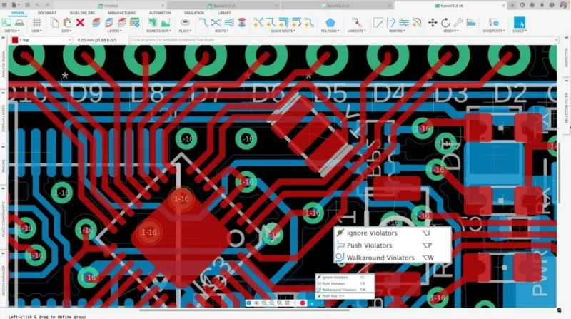
Photo: PCB design rule check software engineer circuit board review, via www.globalwellpcba.com
There is a particular kind of confidence that settles over an engineering team the moment a design rule check completes without errors. The software has spoken. The board is clean. The files go to fab. What follows, in a troubling number of cases, is not a manufactured board but a phone call—or worse, a formal DFM rejection report—informing the team that the design cannot be produced as submitted.
This scenario plays out across American electronics firms with quiet regularity. The financial consequences range from irritating to catastrophic: expedite fees, respin costs, delayed product launches, and in competitive markets, the permanent loss of a window. Understanding why DRC passes when the design fundamentally cannot be manufactured requires a clear-eyed look at what design rule checks actually do—and what they were never designed to do.
What DRC Actually Checks (and What It Does Not)
Design rule checks operate against a rule set. That rule set is only as accurate as the data used to populate it. Most CAD platforms ship with default rules that are either generic industry approximations or values inherited from a previous project's library. Unless an engineer has deliberately imported a fabricator's specific process capabilities and mapped them correctly to the tool's constraint manager, the DRC is essentially checking the design against a set of assumptions that may have no relationship to the facility that will actually print the board.
This gap is more common than the industry typically acknowledges. A 3-mil minimum trace width may pass in software configured with legacy defaults, while the targeted fab's current process floor sits at 4 mils for the copper weight specified. Annular ring calculations may not account for drill registration tolerances on a particular panel size. Copper-to-edge clearances may satisfy the rule set while violating the router's physical limits on the production floor.
The software reports zero violations. The fabricator reports an unprintable design. Both statements are technically accurate, and that is precisely the problem.
The Misconfiguration Problem Is Structural, Not Accidental
It would be convenient to frame misconfigured DRC rule sets as a careless oversight—something a more attentive engineer would catch. The reality is more structural. Rule set management is rarely treated as a formal engineering deliverable. In many organizations, no single person owns the constraint library. Rules are copied from project to project, updated inconsistently, and seldom audited against current fab capabilities.
Fabricators also evolve. A facility that ran 3-mil traces reliably three years ago may have shifted its process floor, updated its equipment, or changed its yield thresholds in ways that never propagated back to the design teams it serves. Without a formal mechanism for synchronizing fab capabilities with internal rule sets, the drift accumulates silently.
Compounding this is the reality that many DRC tools do not check for manufacturing intent—only geometric compliance. A via that is technically within minimum annular ring spec may still be unfabricable if it is nested in a high-density region where the drill-to-copper proximity creates consistent yield failures. The rule passes. The board fails. The distinction is invisible to the software.
Where Reviews Break Down
Design reviews are supposed to catch what DRC misses. In practice, they frequently do not. Peer reviews tend to focus on functional correctness—signal routing, component placement, power distribution—rather than process compliance. Reviewers often share the same assumptions embedded in the rule set, which means they are unlikely to surface the constraints the rule set failed to capture.
External DFM review, when it occurs at all, is typically scheduled late in the design cycle, after significant layout work has been completed. At that stage, the cost of acting on a DFM finding is high, and the organizational pressure to proceed is intense. Findings get logged, deferred, or minimized. Some make it to production. Some produce field failures.
The structural fix is not a better review checklist. It is a different sequencing of constraints—one that introduces manufacturing reality earlier in the design process, before layout decisions calcify.
Building a Framework That Catches What CAD Misses
Several practices, when applied systematically, meaningfully reduce the gap between a passing DRC and a manufacturable design.
Source constraints directly from your fabricator. Many US fabricators publish detailed process capability documents, and some provide CAD-compatible rule files for common platforms. Treat these as living documents. Establish a review cadence—quarterly at minimum—to confirm that internal rule sets still reflect current fab capabilities. Assign ownership of this process explicitly.
Run independent DFM analysis before layout completion. Tools such as Valor NPI, Cadence Allegro's DFM extensions, and several third-party platforms perform manufacturing analysis that goes beyond geometric DRC. They evaluate copper density, drill-to-copper proximity, solder mask slivers, and other conditions that standard DRC tools ignore. Running these checks at 60 to 70 percent layout completion—rather than at tape-out—preserves the flexibility to act on findings without triggering a full respin.
Distinguish between rule types in your constraint manager. Not all DRC rules carry equal manufacturing weight. Trace width minimums, annular ring floors, and copper-to-edge clearances are hard process limits. Other rules—such as courtyard overlaps or silkscreen conflicts—are functional concerns that may not affect fabricability. Tagging rules by category and severity helps reviewers prioritize findings and prevents critical manufacturing violations from being treated as cosmetic issues.
Conduct structured fab-to-design feedback loops. When a fabricator issues a DFM rejection or raises a process concern, that information should flow back into the rule set, not just into the current revision. A rejection that corrects a single board but leaves the underlying rule set unchanged will produce the same problem on the next project. Treating fab feedback as rule set input rather than one-time correction is a discipline that compounds over time.
Involve process engineers in design review. Engineers with fab-floor experience read a layout differently than those whose primary context is schematic and simulation. Where a layout engineer sees a compliant via field, a process engineer may see a drilling registration risk. Cross-functional review does not require restructuring the organization—it requires deliberately including the right perspectives at the right stage.
The Cost of Waiting for the Fab to Find It
The economics of late-stage DFM failures are well understood by anyone who has lived through one. A finding caught during constraint setup costs an hour of rule adjustment. The same finding caught at DFM review costs a day of layout revision. Caught by the fabricator after file submission, it costs a respin cycle—typically two to four weeks in a best-case scenario—plus expedite fees, re-qualification time, and the downstream schedule compression that propagates through the entire program.
In markets where launch timing is a competitive variable, those weeks carry a dollar value that dwarfs the investment required to prevent the problem. The engineering discipline to close the gap between DRC compliance and genuine manufacturability is not a quality initiative. It is a business imperative.
A green light from the rule checker is a necessary condition for tape-out. It has never been a sufficient one. The teams that understand that distinction—and build their workflows accordingly—are the ones that ship on time.